I started this little blog as a portfolio for my ideas and experiments. 5 years later everything is changing again and I have decided it is time to start a company so I can properly give "wings" to all my little things! The company is called MefistoFiles, note that the 'ph' has been removed in favour of a more spanish 'f' ;-)
So we are leaving blogspot and the blog will continue in the new web: http://mefistofiles.com/experiments
To celebrate I think I will publish there a new entry about a VR experiment I did a few month ago... I am sorry I always do this so many months after the projects.
Thanks for reading and see you in the new web!
VR Blink Detection
In December 2015 I was invited to Granada Gaming, a Video-games festival held in my home town, to talk about VR and my interaction experiments. Very exciting times!
I had to give two talks: the first one was oriented to all the professionals (coders, artists, journalists) where I explained some of the decisions I took while creating Apnea (my always in-progress videogame). The second talk was for a general public and for this one I wanted to talk about something that seems to concern a lot of people: VR limitation and why FPS won't work very well at the beginning.
I won't cover the whole talk here as many of the interaction experiments showcased can be found already in the "VR Wireless" post and my github page, but I created something I thing is a cool hack to solve one of the main trends in VR movement: the blink transition.
Moving the FPS way in VR with a gamepad causes nausea to pretty much 45% of the players (nDreams CEO dixit) so companies are coming up with a lot of creative solutions to workaround this problem.
One of the main solutions is called blink transition, and it has been popularised by great experiences such as Epic's Bullet Train and GearVR game Land's end.
With this solution you basically look at the point where you want to move and just press a button that will teleport you there. This transition sometimes happen by closing and opening virtual eyes in front of the user or simply lerping him there really fast.
While it's true that this technique usually does not cause any nausea it is a big presence breaker for me: looking at a point and pressing a button to suddenly be there is not a very natural way of moving... how could I improve it?
What if I could detect if the user is truly blinking? Instead of closing some fake eyes in front of the player and having to press any button it will feel like a super power, think about NightCrawler from the X-men. This will suddenly make the movement system way more natural and amazing, improving the presence factor a lot while being more enjoyable and comfortable.
Some experimental HMDs are starting to support eye tracking, the most notorious one being the FOVE HMD: if you can track the user's eye it has to be trivial to detect if it's closed. But all I had in my hands was a GearVR for Galaxy Note 4, some hacking was needed.
I realised that the GearVR has some covers in the front to prevent scratching the phone when attached. If you remove any of this plastic-covers.. voilá! there is a screw!
Front facing you, the top right screw just happens to be exactly inlined with the Note 4's front camera! I inspected the Galay S6 GearVR and seems to be the same case. -What a lucky coincidence!- I thought - if only I could use this camera to track the user's eyes...
Then a new idea came to my mind: I don't need to track the eye, I just want to know if it is opened. When you look at someone's eyes they happen to reflect a lot of light, but when you close them your skin is not near as reflective.
If I create a very bright scene my eye will reflect a lot of light and maybe some will reach the front facing camera. But that was not the case, the camera (even thought I removed the screw right in front of it) was still too far away and angled to read this subtle amount of light. A visit to the store will solve this: 10 cm (2£) of optical-fibre: If I put one end in the screw's hole facing directly the camera and the other end facing the eye I can redirect the light from the screen -> to the eye -> to the cable -> to the camera!
All that rested was to create an ultra-simple script that will read the amount of light received: just add the value of all pixels and check if it's higher than a threshold. Thanks to Unity and Android I can control the resolution and discovered than using a 20x20 texture was good enough so the calculation was lightning fast... even detecting the fastest blink. For obvious reasons I set that the eye had to be closed for around 500ms or the user will be travelling surely more than desired.
Here is a video. The black square is the camera input, you can see the amount of light received (multiplied by a very very big factor) and how it becomes pretty much black when I close my eyes:
My last problem was with Android 4.4.4 and the camera sensitivity. It seems that they added some enhancements in Android 5, but with my version I could not control the shutter, so sometimes it was not sensitive enough to read the light. The solution i quite lame, just sightly remove the phone from the HMD (while keeping the USB connected) so a lot of light comes inside the camera this will adjust the shutter from you and everything will be fine!
This was so simple/cheap to do (and so useful!!) that I would love future HMDs to come at least with some sort of blinking detection. VR movement sure is an interesting problem and when deciding between presence or not-sickening every little can help.
I had to give two talks: the first one was oriented to all the professionals (coders, artists, journalists) where I explained some of the decisions I took while creating Apnea (my always in-progress videogame). The second talk was for a general public and for this one I wanted to talk about something that seems to concern a lot of people: VR limitation and why FPS won't work very well at the beginning.
I won't cover the whole talk here as many of the interaction experiments showcased can be found already in the "VR Wireless" post and my github page, but I created something I thing is a cool hack to solve one of the main trends in VR movement: the blink transition.
Blink transition
Moving the FPS way in VR with a gamepad causes nausea to pretty much 45% of the players (nDreams CEO dixit) so companies are coming up with a lot of creative solutions to workaround this problem.
One of the main solutions is called blink transition, and it has been popularised by great experiences such as Epic's Bullet Train and GearVR game Land's end.
With this solution you basically look at the point where you want to move and just press a button that will teleport you there. This transition sometimes happen by closing and opening virtual eyes in front of the user or simply lerping him there really fast.
While it's true that this technique usually does not cause any nausea it is a big presence breaker for me: looking at a point and pressing a button to suddenly be there is not a very natural way of moving... how could I improve it?
Blink detection
Some experimental HMDs are starting to support eye tracking, the most notorious one being the FOVE HMD: if you can track the user's eye it has to be trivial to detect if it's closed. But all I had in my hands was a GearVR for Galaxy Note 4, some hacking was needed.
I realised that the GearVR has some covers in the front to prevent scratching the phone when attached. If you remove any of this plastic-covers.. voilá! there is a screw!
Front facing you, the top right screw just happens to be exactly inlined with the Note 4's front camera! I inspected the Galay S6 GearVR and seems to be the same case. -What a lucky coincidence!- I thought - if only I could use this camera to track the user's eyes...
Then a new idea came to my mind: I don't need to track the eye, I just want to know if it is opened. When you look at someone's eyes they happen to reflect a lot of light, but when you close them your skin is not near as reflective.
If I create a very bright scene my eye will reflect a lot of light and maybe some will reach the front facing camera. But that was not the case, the camera (even thought I removed the screw right in front of it) was still too far away and angled to read this subtle amount of light. A visit to the store will solve this: 10 cm (2£) of optical-fibre: If I put one end in the screw's hole facing directly the camera and the other end facing the eye I can redirect the light from the screen -> to the eye -> to the cable -> to the camera!
 |
| The camera end of the cable |
 |
| The eye end |
All that rested was to create an ultra-simple script that will read the amount of light received: just add the value of all pixels and check if it's higher than a threshold. Thanks to Unity and Android I can control the resolution and discovered than using a 20x20 texture was good enough so the calculation was lightning fast... even detecting the fastest blink. For obvious reasons I set that the eye had to be closed for around 500ms or the user will be travelling surely more than desired.
Here is a video. The black square is the camera input, you can see the amount of light received (multiplied by a very very big factor) and how it becomes pretty much black when I close my eyes:
My last problem was with Android 4.4.4 and the camera sensitivity. It seems that they added some enhancements in Android 5, but with my version I could not control the shutter, so sometimes it was not sensitive enough to read the light. The solution i quite lame, just sightly remove the phone from the HMD (while keeping the USB connected) so a lot of light comes inside the camera this will adjust the shutter from you and everything will be fine!
This was so simple/cheap to do (and so useful!!) that I would love future HMDs to come at least with some sort of blinking detection. VR movement sure is an interesting problem and when deciding between presence or not-sickening every little can help.
Hack 'n Slash
October 2014 came fast and I was ready for another HackManchester after having a blast the previous year. But this time having to work +60 hours in a week made me take the decision of doing something much simpler so I could get some sleep.
At this point I was starting to experiment with an idea for what later will become Apnea, my first ever commercial/experimental game (still in the making... but more on this on another post). One of the key features of Apnea was the detection of the user steps using the HMD's accelerometer and another one was the detection of the user breath with the microphone. Soon I realized I had a problem: every time the user walked very strange signals appeared in the breath detector, quite odd! I fixed those problems much later, but by that time I decided what if I make a small interactive game out of this odd behaviour?
The idea was named Hack 'n Slash (thanks Tom!) and it basically is a fencing game using sticks and smart-watches!
In order to play you will need:
- 2 Android smart-watches (I used t LG ones)
- 2 Android smartphones (I used a Moto G and a Nexus 7)
- 2 players
- 2 swords (anything from wooden stick to foam sword)
The rules themselves are pretty simple, each player as 5 lives and every time they are hit by the other player in the body they will lose one. When a successful hit is landed the players will have 2 seconds to go back into the initial position before starting fencing again.
But how does it work?
Hit landing
Detecting that a sword is hitting an object is not a trivial task, a first naive approach would use the smart-watch accelerometer to detect that the user arm has suddenly stopped/changed course , but this would generate a lot of false positives as the swords are moving really fast in the air causing a lot of noise in the acceleration signal. Here is where the Apnea problem comes into play.
When the sword actually hits something it will micro-vibrate and this vibration will get translated to the user hand and wrist. If only we had a reliable way to read vibrations... but we do! The microphone in the smart-watch is an air-vibration detector that we can "easily" convert into a "wrist-microvibration detector".
- Easy - Tape the microphone hole and maybe put some blu-tack on top of the tape so no air can come in at all.
- Easier - Wear the smart-watch, preferably on top of the big bone of your wrist.
- Not so easy - now we need to read the microphone data and identify the microvibrations of the wrist. If the sword hits something the bones will vibrate and the isolated microphone will catch up some noise. Since the bones are solid we are interested just in low frequency vibration, using the Fourier transform over the noise signal and reading just the lower values (using an empirical threshold) we can determine that a hit has landed! This can be further improved by mixing this data with the accelerometer peaks.
Hit synchronization
When player 2 hits something successfully the watch will inform his paired phone using the Google APIs and this phone will tell, using sockets, the player 1 phone (the server). Player 1 watch obviously communicates directly with the server-phone.
The server will then calculate if both players have registered a hit roughly at the same time (around 100ms difference) this will indicate either a draw: both player hit each other at the same time, or a clash: one sword hit the other. If none of these situations happened then the player that did not send a hit on time will lose a live and the system will close the communications for 2 seconds so the players can go back to the initial position.
Socket communication was fast enough and was adding just a 10ms delay... but the Google system to communicate watch2phone was incredibly slow (around 300 ms). How could I detect simultaneous hits?
The solution for this in the end was quite simple: after successfully pairing watches and phones both players will clash their swords to start the match. This, apart from looking cool as some sort of fighting ritual, will allow the program to measure the starting time difference between the two players. Then when a hit is send they will add a time-stamp taking in count the time difference measured at the beginning. The result was great: A sword clashing will look like 2 simultaneous hits just 5ms apart or so!
The code
Light Raider
Half a year after HackManchester I decided to give a go to a Data-Based Hackaton... this time joining a team with friends. The result was the Light Raider, an Android app that encourages running among Mancunians by targeting lamps in the streets. It went really well as we won in "life quality" topic ... and I used tha tmoney to get me an Oculus Rift SDK 2 (but that is a different story) and we even got showcased by some of the local media.
 The Hackaton was organized by the Greater Manchester Data Synchronisation Programme (GMDS) They offered a very wide variety of open data from Greater Manchester's councils, and it was the "competitors" role to create new and interesting applications and services that are able to communicate with the datasets in order to create a more intelligent city.
 Light Raider is an Android game that uses some concepts from Ingress, RunKeeper and Tamagochi to make users go out and run. In this game, the user has a pet (a light bulb) that is constantly demanding to be fed with energy, so every 1-2 days the user must go out and retrieve some energy in order to keep it alive... and here is where the game gets interesting. Once the player decides to go out running, the view changes to a countdown and the user must retrieve energy faster than it drains in order to fulfil the "batteries" of the light-bulb. To do so all street-lamps around the phone are retrieved from the council's data set and, every time the user pass by a new lamp, the energy levels go up a little bit.
The Hackaton was organized by the Greater Manchester Data Synchronisation Programme (GMDS) They offered a very wide variety of open data from Greater Manchester's councils, and it was the "competitors" role to create new and interesting applications and services that are able to communicate with the datasets in order to create a more intelligent city.
Of all the datasets that we could choose we loved the ones that store the information of every street-lamp in a council... and as the topic: improve Mancunian's quality of life. After thinking hard and many discussions we decided to take one of my original ideas and mix it a bit: Light Raider.
Light Raider is an Android game that uses some concepts from Ingress, RunKeeper and Tamagochi to make users go out and run. In this game, the user has a pet (a light bulb) that is constantly demanding to be fed with energy, so every 1-2 days the user must go out and retrieve some energy in order to keep it alive... and here is where the game gets interesting. Once the player decides to go out running, the view changes to a countdown and the user must retrieve energy faster than it drains in order to fulfil the "batteries" of the light-bulb. To do so all street-lamps around the phone are retrieved from the council's data set and, every time the user pass by a new lamp, the energy levels go up a little bit.
Sounds easy? It is not. On running mode the light-bulb's battery drains quite fast and requires the user to actually run. But also the lamps visited by the user are remembered... which means he has to conquer new ones every time.
Still easy? Ok! It is not only about visiting new lamps. In the map the user can see which lamps have been"raided by other players already and he will need to reconquer his territory if he wants to score high in the general competition. If the pet dies (not getting energy for a few days) all the attached lamps are freed and the general score goes back to 0.
With this system for micro (pet energy) and macro (lamps raiding) "encouraging system" the user should have enough motivation to go out and do a bit of exercise hopefully!
The Wireless VR Experience
After leaving my VR Gun project for a while I decided to go to HackManchester 2013 and give it the push it deserves by creating not just the Gun, but a full VR experience. In 25 hours I managed to finish the weapon and modify an existing game named Angry Bots to be playable with all the freedom of a wireless system!
I won the "Best Company Project" award from the jury, and also was the finalist (2nd) for the "Best of All" competition. A true honour that motivated me onto polishing and showcasing the project for the Manchester's Android Meetup months later with huge success :-)
Ok, so what is this exactly? Basically it is a set of applications to detect the user's movements to control and display a FPS version of the mentioned game. The user experiences a 3D environment that allows him not only to look around using stereoscopic vision, but walk, jump. crouch, aim... a full VR experience; and most importantly: in Real Time, without any cables and ultra-light, perfect for feeling deeply immersed.
All code can be found in my Github, I will explain here the key parts of the project, which are summarised in the presentation I used or the Android Meetup and can be found here.
 Through an OTG cable, the board is connected to a Galaxy S3 attached to the Gun itself running a very particular app. The app, inside DataStreamer folder, will listen to the Arduino output and also track the pose. The phone then has all the important information related to the weapon and can send it to the server (game). But not only that! Because the phone is in contact with the gun and knows when the trigger is pressed I also implemented some haptic feedback so, when the user fires the gun vibrates with a nice machine-gun rhythm.
Choosing the right phone is not as easy as it seems:
Galaxy S3 works wonderfully but still there are some scenarios where the user will have to hit the button every 5 minutes or so... until I code a proper solution (already found one but it has not been implemented yet, more in the last paragraph), and the 5V requested from the OTG makes the battery drain quite quicly (1h-2h).
For the movement I used a different phone running a pedometer, also bundled in the DataStreamer app, I created for my old Augmented Reality system. The important thing about this pedometer is that it not only listens to the strength of the steps but the rhythm so it is very resistant against noise, it could even run directly on the helmet! But instead I decided the user will put it in his back pocket, this way it can track the hip orientation and even the butt inclination.... this way the user could walk towards his hip and not his head and even crouch on real time or even lay down in the ground.
Because, as mentioned in the previous point, not all phones have a RT-compliant gyroscope, I decided to put a toggle button to disable the hip-butt pose detection and use the head tracking instead in case the phone is not powerful enough to keep the pose updated without breaking the immersion.
This is the most important part. I created a helmet out of foam during the Hackaton (that later was substituted by a more professional-looking black helmet) that holds a 7" tabled (Nexus 7) and 2 lenses to the user's face. The code running here is in the VRUnity folder and contains a Unity3D project. It is the Angry Bots demo game modified in two ways:

The biggest task here was not only finding what was not working with the OR SDK (it was not crashing, it was actually working but my communication system was not.. and it was its fault) but also creating the helmet. There are a few small details to have in count:
The first version was not the best; but after many tries, super-glue, cutting and breaking elastic bands I built a black helmet following all those guidelines.
The way everything works together is thanks to some UDP magic. The DataStreamer apps will bundle the information in Datagram packages and send it to the server (game). Once the game receive the package, it has to parse it and redirect it to the relevant Gameobjects that will apply the information.
The key for having RT here was to use a port for each possible message (fire mode, hip pose, steps, gun pose, etc.) so there is a file defining a set of offsets for the port and each listener will apply it when sending the datagram. On the server side there is one thread running per port, each of these threads is looking for exactly one type of message and as soon as it is received it is processed.
What's next:
There are a few bits I am still not happy with and I will try to solve at some point.

I won the "Best Company Project" award from the jury, and also was the finalist (2nd) for the "Best of All" competition. A true honour that motivated me onto polishing and showcasing the project for the Manchester's Android Meetup months later with huge success :-)
All code can be found in my Github, I will explain here the key parts of the project, which are summarised in the presentation I used or the Android Meetup and can be found here.
The Gun:
The gun used is obviously my VR Gun. I coded the Arduino board so I could actually track the on/off positions (only on first-call) for the trigger and the ammo clip modifying the original's Makey Makey code.Choosing the right phone is not as easy as it seems:
- It needs to have not only OTG support but to be able to give it a 5V input.
- The pose-detection relays strongly on the gyroscope sensor and, nowadays, it is quite difficult to find information about how good a phone's gyroscope is. I tried my best to correct any drifting using a version of this code, that brings accelerometer and compass to the mix in order to create a rock-solid pose reading, but can still be problematic in medium/low-end phones. For that reason I included a huge Sync button in the middle of the screen so it is impossible to miss it while playing and will realing the head, hip and head poses.
Galaxy S3 works wonderfully but still there are some scenarios where the user will have to hit the button every 5 minutes or so... until I code a proper solution (already found one but it has not been implemented yet, more in the last paragraph), and the 5V requested from the OTG makes the battery drain quite quicly (1h-2h).
The Movement:
Because, as mentioned in the previous point, not all phones have a RT-compliant gyroscope, I decided to put a toggle button to disable the hip-butt pose detection and use the head tracking instead in case the phone is not powerful enough to keep the pose updated without breaking the immersion.
The Helmet:
- The player has been removed and the camera replaced, after importing the Oculus Rift SDK, with a stereoscopic set of cameras that render the view with the perfect oval shape for the lenses and also track the head's pose very fast. Since OR is PC only, I had to modify the code a bit so it won't silently crash on my device. Specifically I commented out all the code related to DeviceControllerManager and the DeviceImposter.
- I included a communication system to allow the DataStreamer app to send data to the game. More in the next point.
The biggest task here was not only finding what was not working with the OR SDK (it was not crashing, it was actually working but my communication system was not.. and it was its fault) but also creating the helmet. There are a few small details to have in count:
- It has to be closed and dark so the light does not distract the eyes.
- The distance eyes-lenses-screen is very important and varies depending on the user. I ended up creating a couple of rails in my last helmet so it was adjustable.
- Breathing is an issue. There has to be an aperture for the nose or the screen/lenses will be steamed in a few seconds.
- It has to be light, but still avoid any kind of wobbling.
The first version was not the best; but after many tries, super-glue, cutting and breaking elastic bands I built a black helmet following all those guidelines.
The Communication:
The way everything works together is thanks to some UDP magic. The DataStreamer apps will bundle the information in Datagram packages and send it to the server (game). Once the game receive the package, it has to parse it and redirect it to the relevant Gameobjects that will apply the information.
The key for having RT here was to use a port for each possible message (fire mode, hip pose, steps, gun pose, etc.) so there is a file defining a set of offsets for the port and each listener will apply it when sending the datagram. On the server side there is one thread running per port, each of these threads is looking for exactly one type of message and as soon as it is received it is processed.
What's next:
There are a few bits I am still not happy with and I will try to solve at some point.
- I would love to take advantage of the current 3D printers and get a more professional helmet done. I am already talking to a few people and this might be happening soon! In that case I will put the model here.
- Gun drifting. As I mentioned, after a few minutes the gun pose might have drifted a bit. If the tablet in the head had a camera I could set a few LEDs on the gun's nose, flickering with different patterns, and then track it directly from the game. This will even allow to move the gun in a complete 3D space (when in view). I still want the user to be able to fire backwards, in that case the normal gyroscope reading can be used and when it comes back to the front view the drifting (if any) can be corrected again.
- Jump! I already did a few experiments, but it will be interesting to detect jumps using the pedometer code. So far the results make me feel very dizzy after a couple of tries.
- Use a more professional gun, maybe modify an electronic air-soft gun so the weight and controls feel more real.
The virtual reality Gun controller
A lot of things have happened since the last update. Being the most important one that I achieve to get a job in the augmented reality industry! This has keep me very busy for the last year, but I have effectively managed to learn a lot in the field and also Android, iOS, Unity3D and many... many more. I love it!
Now that my "learning" curve has eased out I finally got time to carry on in my personal projects / hacks. And this time I promise I will put some proper code and tutorials (by the way I have enabled the comments so feel free to comment code in the older entries).
So this first new entry is related to the fact that I just received an Oculus Rift. This HMD is called to push the VR back in the trenches and I wanted to try it first hand... It promises real-time head tracking and perfect 3D vision of the environment with an epic field-of-view. You can move around the scenarios and after 3 minutes you truly believe you are inside. But head tracking is not everything in Virtual Reality and there is still some edges to cut: one of those is solving the problem of "moving around" with some kind of localization and I will talk about that one at some point; but the interesting one today is interacting with the environment, and when I say interacting I mean shooting at things... time for some Virtual Reality FPS.
I want to create a Gun that I could use in a shooter game, kind of the one Nathan has created for Half-Life 2 here. But that gun has some drawbacks (economic drawbacks because he is buyin a custom weapon and a custom tracker) and I want something cheap and nice and custom and hacky and ... and ... and I want it now. So this and the next posts will talk about creating your very own Gun Controller with tracking and everything for playing in virtual worlds!
The trigger system works with the same principle but looks sightly different. In top of the trigger piece there are 2 little plastic steps that prevent the moving part to move up and down. With the happy outcome that the second step is only touched by the trigger when pressed! Some tape as in the photo should do it, always remembering to put some tape in the top of the trigger (will be visible in the next photos) and connecting each cable to ground and an input pin in the board.
And finally the ammo clip. This one is a bit more trickier, after struggling about how to close a circuit with a piece that feels always so fragile (it moves a lot inside the cabin) I have a great idea while drying my clothes: clothes peg springs.
The final bits include guiding the cables from the tape areas to the board. The Alpha Trooper has enough room behind the trigger to do so. But on the other side of the gun a little flap must be removed.
The second part is guiding it out of the Gun, the cable goes the same way behind the trigger but needs to come out from the bottom. With the help of the solder or the saw to make some holes in the plastic the USB should go thought the piece 12, then under the trigger spring, under the trigger connection and finally go over the removed flap in the last step.
Now that my "learning" curve has eased out I finally got time to carry on in my personal projects / hacks. And this time I promise I will put some proper code and tutorials (by the way I have enabled the comments so feel free to comment code in the older entries).
So this first new entry is related to the fact that I just received an Oculus Rift. This HMD is called to push the VR back in the trenches and I wanted to try it first hand... It promises real-time head tracking and perfect 3D vision of the environment with an epic field-of-view. You can move around the scenarios and after 3 minutes you truly believe you are inside. But head tracking is not everything in Virtual Reality and there is still some edges to cut: one of those is solving the problem of "moving around" with some kind of localization and I will talk about that one at some point; but the interesting one today is interacting with the environment, and when I say interacting I mean shooting at things... time for some Virtual Reality FPS.
I want to create a Gun that I could use in a shooter game, kind of the one Nathan has created for Half-Life 2 here. But that gun has some drawbacks (economic drawbacks because he is buyin a custom weapon and a custom tracker) and I want something cheap and nice and custom and hacky and ... and ... and I want it now. So this and the next posts will talk about creating your very own Gun Controller with tracking and everything for playing in virtual worlds!
Chapter 1: Ripping apart a Nerf Gun and giving it an Arduino brain.
Lets start from the beginning. In this first chapter I will talk about how I opened a plastic gun and closed a electronic one. I will cover how I made the connections from plastic to Arduino inputs and by the end the result will be a gun being able to fire, reload and select alternative fire. Lights/vibration and tracking will come in the next chapters.
Materials:
The gun: I used a Nerf Gun, the model "Alpha Trooper" have a lot of space inside to maneuver and also looks bad-ass. Actually I bought it to shot foam darts at people at the office... and yes we painted them and everything.
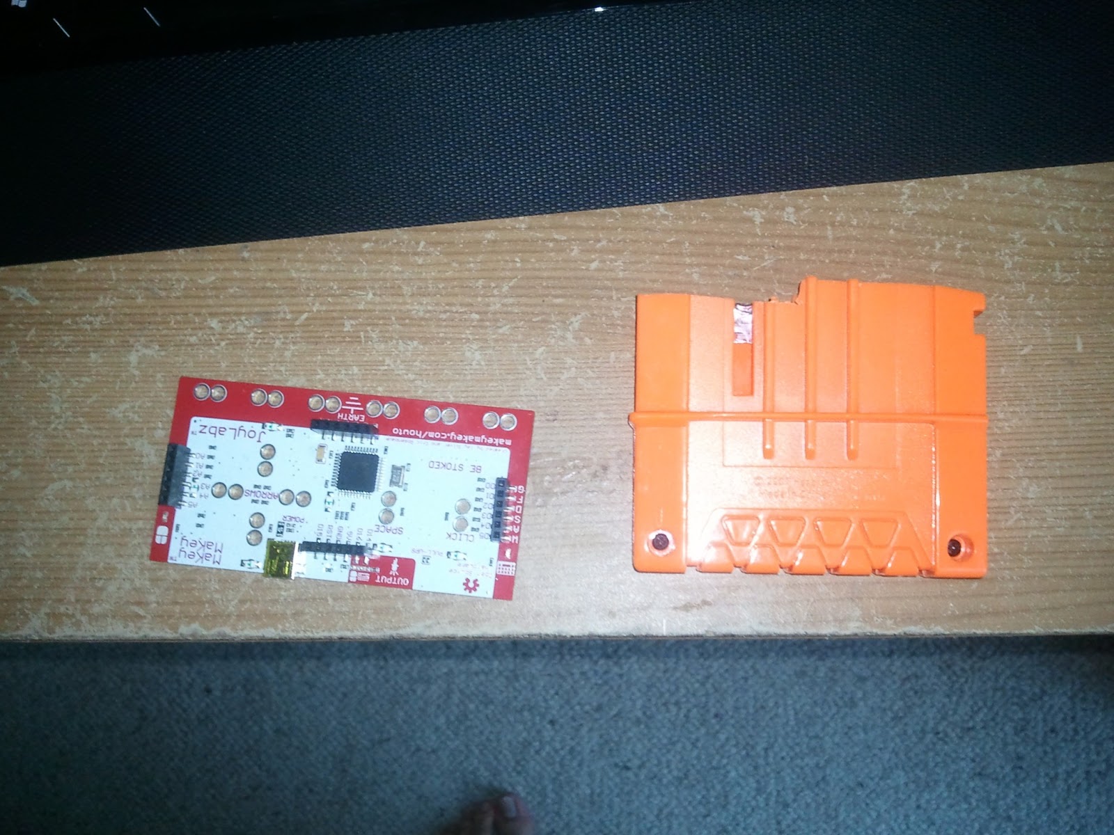
The brain: I have got a Makey Makey, which is basically an Arduino Leonardo. I bought it just to have fun until this project came to my mind! This is not supposed to be a Makey Makey / Arduino tutorial so go to the official forums in case of doubt.
The guts: Some cables, some springs, a solder, a saw, screwdriver and aluminium tape!
Step 1: Unscrew everything
With a star-screwdriver and patience I just simply removed al the screws. Once done, very carefully I removed and keep al the moving-pieces of the gun as you can see in the photo.
 |
| Dismounted Alpha Trooper |
I enumerated the pieces and I will use this photo as reference over and over again. Always keeping all the springs I disposed the pieces 13,14 and 15.
The other big problem is the piece 1. This piece
moves using the side rail and when in "firing" mode takes all the space in the center in order to load the bullet. When cutting it it is important to note that I still needed the 2 hangers for the rails on each side of the gun. And I still wanted to be able to move the piece 4 for realism. So the outcome is cutting to something like this.
Fine! Now I should be able to put the Makey Makey inside, but I still want to be able to remove it sometimes and It must float inside the gun so it does not interfere with the piece 1 moving rails.
I decided to cut a small slot with a saw where the end of the clip should rest. The next photo will highlight this.
Step 2: Making space for the board
As you may see in the top-right corner of the previous photo, the Makey Makey is not very big but I still have to make some room. The picked place is exactly the center, on top if the magazine, but that position will give a couple of problems.
 |
| "resized" clip |
When the ammunition clip is in, it takes almost all the space... so I will cut it with a saw! Always saving the gap in the side that keeps it hooked to the gun.
This picture compares the resize clip to the board. I also removed all the inner parts such as the springs and the platform that you may see in the previous photo.
 |
| "resized" piece1 |
moves using the side rail and when in "firing" mode takes all the space in the center in order to load the bullet. When cutting it it is important to note that I still needed the 2 hangers for the rails on each side of the gun. And I still wanted to be able to move the piece 4 for realism. So the outcome is cutting to something like this.
 |
| A 1cm cut to serve as slot for the board... |
I decided to cut a small slot with a saw where the end of the clip should rest. The next photo will highlight this.
 |
| Cutting in half the piece 11 |
Last, the piece 11 which serves as chamber for the foam bullet is also in the way. Show no mercy removing the right side of it. Always keeping in the "right" side the two small legs to attach it to the body.
And now it the gap is big enough the Makey Makey should fit inside and don't move at all, it is important to note that the piece 1 must be in first, and be sure that its movement is not blocked by the board.
 |
| The Arduino board inside the Gun with all pieces |
Step 3: Making the triggers talk
The real fun starts now. With some aluminium tape and cables the trigger (piece 3), pump system(piece 2) and the magazine should inform to the Makey Makey of their state.
To do so I followed this principle: moving part should now have any cables but being used to close circuits "printed" in the fixed pieces. How does this apply? Easier than it sounds, simply put aluminium tape in the moving parts that, when in on position will touch other 2 aluminium pieces connected to the board. Let's see some close ups.
 |
| Pump system circuit |
This is the edge of the piece 2. Some aluminium tape in the orange part that moves as the very-nice-orange-arrow indicates will connect the red and green areas. It is important to note that the tape must be flat enough to avoid giving too much friction to the moving part. Note how instead of putting directly the cable I allow a big and separated area in the "tape circuit". This cables should go to ground and a input pin in the board later.
 |
| Trigger system circuit |
 |
| Reload system circuit |
Two hard metal springs glued strategically in the gun side, so they block partially the clip entrance, but still holds will do it. Always putting some aluminium tape in the clip so it connects both springs which have cables going to the board as always.
 |
| Flap to remove in the left side |
The final bits include guiding the cables from the tape areas to the board. The Alpha Trooper has enough room behind the trigger to do so. But on the other side of the gun a little flap must be removed.
Removing it will allow some space to guide all the cables through when closing it.
And the very final thing is the USB cable, this step is a bit special, eventually this mod will be wireless with the help of an android phone, but for now an USB connection to the PC is needed. The default cable that comes with the board is a normal mini-usb that won't fit properly between the board connector and the piece 6 so it is important to get a mini-usb with the mini-head output rotated 90 degrees. This is not easy to find in stores as they come customised directly with some cameras. Lucky me a friend gave me one.
 |
| Path for the USB cable |
In the photo I left in red the places where I made a hole, blue for the x-ray vision on the cable and green for highlighting where I removed the flap (in the other side). Please note that here I am not using the 90 degrees cable but the normal one.
Step 4: Test and close
It is time to seal this mess and give it a try. For doing all that is needed is to simply connect the USB cable to the PC and check if and only if one of the circuits is closed the LED in the board goes green. Pro tip: change the current springs in the gun with those removed from previous pieces in order to have stronger springs in the modified parts.
Now turn to put all the items in and put back the screws.
 |
| It is alive! |
 |
| Final look opened |
 |
| Final Look Closed |
Next Step: Programming and LEDs
My next step in the agenda is to do some custom programming to the current Makey Makey script in order to fire the keys for the clip and pump just once when the clip is removed or the or the lever pressed. And also add some AND gates to the trigger so it only shots if there is a clip in possition.
I would also love to add some funny LEDs arrays behind the piece 7 and animate them when doing actions so stay tuned.
After that another post should come with some info about how to make this all wireless and do some tracking using the gyroscope of an Android phone.
Applications for the AR system

One of the advantages of the AR system developed is the ability to couple the logic of a video game. At the same time I was coding the system, my friend Carlos Torija was designing a video game, he created the artificial intelligences and logic and then we both added simple graphics with openGL and gave it some AR. In this game you have to evade/attack an evil drone that follows and tries to kill you. The game has been produced to be played in a open space and it has virtual walls! Next step includes map recognition.
I also started another AR game using my system. I planned to release it for bada 2.0 but Samsung keeps delaying it so the game is unfinished. The game is an augmented stunt kite simulator, at the moment it has really simple physics and fixed wind but I plan to add a wind system using weather forecast and advanced physics in order to perform realistic tricks.

Note: Pink artifacts appears when taking a screenshot and are not present in the real application.
NDS experiments
I know that Nintendo DS is old hardware now, but back in my time it was awesome! One day I discovered PAlib for NDS and I decided to investigate. I came up with some weird ideas, from a back-scratching game to a portable version of the "Shelters of Catan" board game (now it do exists for NDS but it is not my unfinished-experimental version). I also started to program a time-based multiplayer gymkhana game for various teams so they can play in a specific forest, and the clues had to be solved using the NDS.

These projects taught me how hard is to create a game without a real graphical artist in the team, but I also found that seeing your results in a video-console transmits and amazing feeling.
Note: the scratching game is about...that. With difficulty from stinting to herpes and a punctuation system!

Note: the scratching game is about...that. With difficulty from stinting to herpes and a punctuation system!
The home-made VR system.
During my holidays I was growing quite fat due to inactivity and I were spending to much time playing Minecraft. Here at home I have got a dance mat for DDR and those rhythm games but I don't really like them, so I decided to create something funny, healthy and a bit geek: a home-made virtual reality system!
I found GlovePIE, an input emulator where you can create scripts to remap almost any controller, from dance mats to wiimotes. And yes, I have got both of them. I created my first script for Minecraft where you can walk using the dance mat (1 step in real world == 1 step in Minecraft) in a quite realistic way (it is not about pressing one single button, but walking in a natural way) and also jump (the character jumps when you release both feet from the ground so it is almost 1:1). For digging and gather wood you have to shake the Wiimote as if you were using a pickaxe and for putting blocks you have to move the Nunchuk.
Then I started to play Skyrim and so I gained weight again, that's why I remade it! Now it is possible to detect when the user is sprinting, and the script also implements different controls for each weapon: when you are using a sword you need to swing the Wiimote horizontally to perform a light attack and vertically for a strong attack; you can get some cover with your shield raising the Nunchuk and shake it from here to push things with it; you have to raise your hands for controlling spells and, most important, you can use your voice. GlovePIE can easily detect voice commands and in Skyrim this means that it is not only possible to make simple orders like "save the game" or "equip the bow" but you can also shout! So if you want the character to shout the spell "FUS ROH DAH" all you need is to shout it!
Who needs Kinect?
I found GlovePIE, an input emulator where you can create scripts to remap almost any controller, from dance mats to wiimotes. And yes, I have got both of them. I created my first script for Minecraft where you can walk using the dance mat (1 step in real world == 1 step in Minecraft) in a quite realistic way (it is not about pressing one single button, but walking in a natural way) and also jump (the character jumps when you release both feet from the ground so it is almost 1:1). For digging and gather wood you have to shake the Wiimote as if you were using a pickaxe and for putting blocks you have to move the Nunchuk.
I forgot to show how to hit things with the bow shaking the Nunchuk :-(, also voice commands are in spanish.
Who needs Kinect?
Augmented Reality System
After 5 years studying it comes time for the dissertation. You can choose one of the many subjects proposed by the professors , but I decided to go on my own creating a whole augmented reality system.
The original idea consisted in a program that should work in open environments, without markers, trying to naturally fuse the virtual and the real world. In fact those "open environments" were a problem, because giving the user so much freedom can result in low performance visualization when using a smartphone. This was the key point and I wanted to success where other programs such as Layar (poor integration) or AiRaid (lack of freedom) failed.
The system was developed trough a year using C++ and OpenGL for bada smartphones and integrates some new ideas that makes it excels over other AR systems:

- Efficient usage of sensors to obtain a sound registration. This allows the program to work faster in open environments and to avoid possible measurement errors faster.
- Real lightning system. Using GPS-based weather information and sun tracking algorithms in order to get a realistic integration.

In this video the sun movement has been accelerated and the perspective translated for didactical purposes.
- GPS Hybrid. The system can respond correctly even in extreme scenarios, where no accurate GPS data is given, thanks to the advanced pedometer developed.
- Game's logic integration made easy. Programming an augmented video-game is really easy thanks to the well designed system architecture.
This example recreates the worst-case scenario where no GPS signal is received.
For extra information, an explanatory part of the dissertation and many interesting papers about AR can be found here, but I am afraid it is in Spanish. Note:Pink artifacts appears when taking a screenshot and are not present in the real application.
Subscribe to:
Posts (Atom)